void empty(void) { }
libFirm is a C library implementing the Firm low-level intermediate representation. Firm is used to represent a computer program in order to analyse and transform it. Its main application is compiler construction where we use it to represent, optimize and transform C and Java programs to native machine code.
The most important features of Firm are that it is
low-level which means that the representation of the program is closer to machine code than to the language.
completely graph based which means that there are no instruction lists or triple code, only data dependence and control flow graphs.
completely SSA based which means that the code of the program is always in SSA form.
A complete list of Features is also available.
In the following, we will try to give you an idea about how programs are presented in Firm.
Firm is using most of the concepts described by Cliff Click. So for a more "scientific" description you might refer to:
Click, C. and Paleczny, M. 1995. A simple graph-based intermediate representation. In Papers From the 1995 ACM SIGPLAN Workshop on intermediate Representations (San Francisco, California, United States, January 22 - 22, 1995). ACM, New York, NY, 35-49. http://dx.doi.org/10.1145/202529.202534.
A program (called irp in FirmSpeek) in libFirm consists of three things:
A type graph
A list of IR graphs (irgs) representing the code of the functions in the program
A symbol table
Let us review the type and the IR graphs more closely.
Basically, the irg represents a piece of code. In Firm, this piece of code is called a method. An IRG is a directed graph consisting of IR nodes (_irn_s) and edges between them. The irns basically represent the flow of control and data in the code to represent. Hence, there are nodes which describe
basic blocks
control transfer instruction like jumps
data flow operations such as loads, stores, additions, etc.
libFirm has several routines to dump irgs to text files in the VCG format. The yComp Tool is very well suited to visualize these graphs. In the following, we will use these visualizations to present the fundamental concepts of the irgs.
The first irg we will consider is almost minimal. It was constructed by the C frontend of our compiler and represents the code of following C function
void empty(void) { }
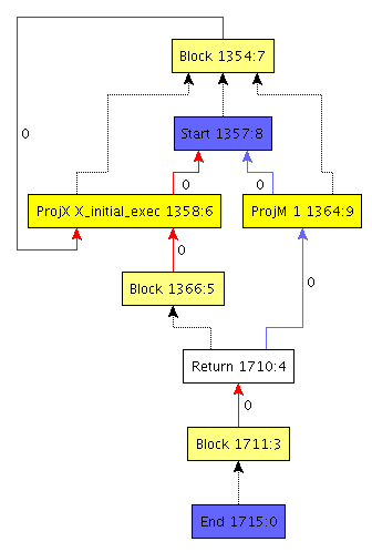
You will notice that there are several nodes in different colors with names and numbers. Furthermore, the edges have different colors, line styles and numbers attached. Let us go through all these elements step by step and meet first peculiarities of Firm.
Each irn possesses two numbers separated by a colon. The first number is unique in the whole program (irp) the second one is unique in the irg. Being unique in the program eases debugging, since each node can be uniquely identified. Having a number per irg is useful for bitsets, or maps using that number to index elements. Therefore the first number is called the node number and the second one the node index.
The two blue nodes Start and End present the source and sink for all data and control flow.
They are the only nodes which are painted in blue so the begin and the end of the program is easy to spot.
The light yellow nodes with the label Block represent basic blocks in a control flow graph.
Nodes can belong to a basic block.
This membership is expressed with the dotted edges.
For example, the End node belongs to block 1711.
The block of the End node is called the end block and the block of the Start node is called start block respectively.
Each block has red edges originating from itself.
These edges are control flow edges. Exceptionally, they are drawn in the wrong direction.
For example, the Return node transfers the control to block 1711 although the edge is drawn in the other direction.
This is due to the internal representation of control flow.
Each block has an array of control flow predecessor nodes, i.e. nodes that transfer the control to it.
The numbers at the control flow edges give the predecessors of a block some order.
This will be important when we will consider Φ-nodes.
One rule in Firm says that each block has at least one predecessor. However, this is slightly contrary to the concept of a control flow graph which has exactly one node which is the origin of control flow and has thus no such predecessor. To maintain this rule a control flow self loop is attached to the start block. This loop is from node 1354 to 1358 in the example. (NOTE: This is not true in anymore in latest firm versions, we have to update the image and remove this text then)
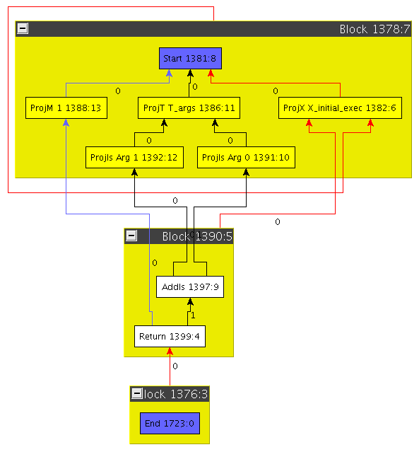
Drawing the block membership explicitly can lead to very non-concise graphs. Following the familiar drawings of control flow graphs, we thus draw basic blocks as big containers in which all belonging nodes are placed. From now on, we will only draw the graphs this way.
Consider the graph on the right.
You might have asked yourself what about these Proj nodes which seem to occur frequently.
One of the Firm axioms is that each SSA value corresponds to a node and vice versa.
For operations which produce multiple results, this seems to pose a problem.
Firm’s solution to this problem is to let that operation return a tuple value out of which the results can be projected.
This is done with Proj nodes. Note that Tuples can also be nested.
In the example graph on the right, the Start node returns a tuple out of which three values are projected.
Node 1388 projects element 1 from the tuple.
Node 1386 projects the element t_args from the tuple, which is itself a tuple.
It contains all arguments passed to the method this IRG represents.
And finally, node 1382 projects the initial control flow (denoted X_initial_exec).
Using Proj nodes to handle multiple return values has pros and cons.
The biggest con is that a Proj does not resemble a real instruction.
The biggest pro is that, using Projs, each SSA value directly corresponds to a node.
This makes a lot of things easier when working on the graphs;
to address a result without Proj nodes, one would have to maintain a pair (node, result number).
Usage of Proj nodes is disputable.
Firm chose to have them.
As you can see, the method on the right really does something, in contrast to the last example.
Node 1397 adds the both operands given to the method.
Its result is returned by the Return node 1399.